Often, users leave the front panel connection to the end of the assembly, paying more attention to the main components of the PC. This approach is reasonable, but one incorrectly connected panel connector will not allow you to turn on the device even if all other components are correctly assembled.
To not face any trouble connecting components to your computer’s front panel? With the right knowledge and patience, you will get all front panels correctly in no time.
This guide will explain what each one from the front panel is used for and how to connect them properly to ensure clarity when setting up your system. So let’s read on!
What are the Front Panel Connectors on the case?
The design of computer cases has changed over the years, and this fate has not bypassed the front panel with connectors. The controls remain unchanged in the form of on / off and reset buttons, indications, audio, and USB ports.
In addition to these main groups of connectors, you can find backlight control buttons in many modern cases. Connecting the backlight of the case can be implemented in various ways, depending on the manufacturer. Often this is a three-pin 5V cable connected to the motherboard and a SATA cable for connecting to the power supply. Another common option is to connect to the built-in controller.
When connecting wires from the front panel, it is advisable to follow the general cable management of the case. Namely, plan and bring the cables before installing the motherboard. Connecting the panel wires is the penultimate step before the finished assembly of the PC. The final step is to install the GPU card, as its size can be inconvenient.
Typical connector layout on the example of ASRock B450M.
The three main categories of connectors have corresponding connectors on motherboards in designated locations, which vary slightly depending on the specific device.
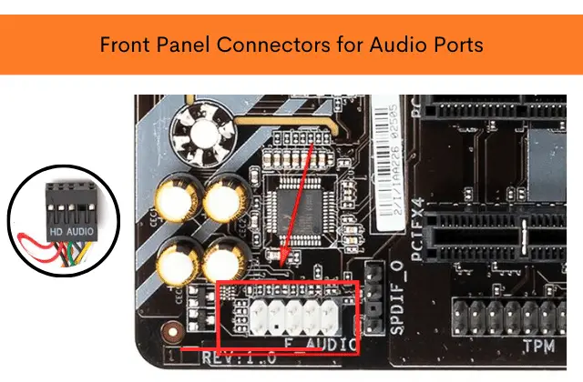
1. Audio connectors
On the front panels of modern cases, you can find two types of audio connectors:
- Separate – separate connectors for microphone and audio output.
- Combined – one connector that combines both interfaces.
Regardless of the type of implementation, the audio connector is connected to the board using one standardized connector. The audio connector is a 9-pin connector, and the tenth block is missing, thus creating a specific structure that does not allow the connector to be connected incorrectly.
As a rule, the corresponding connector on the motherboard form factor is located on its lower left side and is marked HD_Audio. In compact boards, they may not be located in the most convenient places, and the use of processor coolers with a horizontal arrangement can greatly hinder free access to the connector.
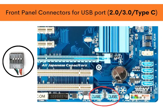
2. USB port
A variety of versions of USB ports have not forgotten computer cases. You can find cases with standard USB ports of different versions, double-sided Type-C, and various combinations.
a. USB 2.0
This type of connector has a 9-pin connector similar to the audio connector but with a different hole pattern – the missing block is on edge. As a rule, you can find the corresponding connector on the board near the massive platform for connecting the power cable on the right side of the motherboard. It is labeled USB. Often there are several such connectors on the board.
b. USB 3.0
Unlike the older 2.0 version, USB 3.0 ports connect with a massive cable and plug. There is a separate fixing frame for the 19-pin connector. The plug has a special key to prevent incorrect connection, and inserting it into the connector with the wrong side will not work. It is also located in a group with other USB ports.
c. USB Type-C
The modern and compact USB Type-C connector is not found in all motherboards, and in order to use the corresponding port in this case, it is worth foreseeing this nuance. This connector has a guide for tight connection of connectors. Its connector is fundamentally different from the previously reviewed USB versions. Instead of pads, “tracks” are used – ten pieces on each side. As a rule, it can be found in a group with other USB connectors labeled USB 3*.
3. PC control and indication
There should be no particular problems with connecting the previously said connectors. But connecting the PC control and display connectors can cause some problems for an inexperienced user. This is due to the many individual wires without physical guides or protection against incorrect connection.
As a rule, the necessary connectors are located on the lower right side of the motherboard and are labeled PANEL or F_PANEL. Connectors of buttons and indicators are divided into groups and placed one after another.
The connection blocks may be arranged in a different sequence depending on the specific board. Therefore, having a quick user guide manual on hand is important that details the board’s pinout. If it is not there, you can use the board manufacturer’s tips, namely the markings next to the pads.
- Power SW/RESET SW: “Reset” button plug
- Power Led +/- : Power LEDs
- HDD LED: a visual indicator of hard drive activity
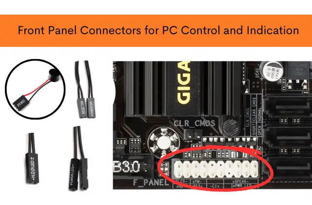
The standard block is a 9-pin connector, and the connectors are connected and labeled down. As a rule, the Power SW on / off button has a dual wire connected to the upper rightmost connector.
The next step is to connect the indicators that indicate the inclusion of the PC Power LED. The required pins are in the same row. Plus is on the far left, and minus, respectively, is to the right.
Next in line is the Reset SW reset button. In this case, it is located on the extreme right and the on / off button, but in the bottom row.
It remains only to connect the indication of the hard drive HDD LED operation. The required connector can be found in the bottom row of the F_PANEL. As in the case of PC power indicators, the positive connector is to the left; the negative one is to the right. Complete with the motherboard or case, the user can find an adapter for connecting the previously announced connectors. The adapter greatly facilitates the frequent connection/disconnection of miniature connectors.